Loading...
Loading...
Loading...
Loading...
Loading...
Loading...
Loading...
Loading...
Loading...
Loading...
Loading...
Loading...
Loading...
Loading...
Loading...
Loading...
Loading...
Loading...
Loading...
Loading...
Loading...
Loading...
Loading...
DJI M3D/T Flight Mode = Normal Mode
DJI M3D/T Maximum Tilt Angle = 25° Degrees
Maximum Take-Off Weight = 1.61 kg (3.55 lbs)
Minimum Deployable Altitude Rating at 1.61 kg = 34.8 m (114.17 ft)
ATS Arming Height = 34 m (111.5 ft)
Maximum Operational Altitude = 120 m (400 ft) AGL
Manual Triggering Device Range = <8 km (<4.97 mi)
Manual Triggering Device Arming Height = 5 m (16.4 ft)
Temperature Range = -20°C to +45°C (-4°F to 113°F)
Ingress Protection (IP) Rating = IP54
EASA MOC2512 Wind Limit = 9.01 m/s (17.5 kts)
ONLY FLY THE DJI M3D/T IN NORMAL MODE.
THE PRS-M3DTEX MUST BE FLOWN ABOVE THE MINIMUM DEPLOYABLE ALTITUDE FOR OPERATIONS OVER PEOPLE, WHICH IS 34.8 M (114.17 FT) OR HIGHER.
ALWAYS FLY THE DJI M3D/T WITH THE DOWNWARD-FACING SENSORS ENABLED. FAILURE TO DO SO WILL RESULT IN THE PRS-M3DTEX ATS BEING UNABLE TO DISARM WHEN LANDING.
IT IS NOT RECOMMENDED TO CHANGE / SWITCH FLIGHT MODES FROM NORMAL MODE TO AUTOMATED FLIGHT MODES OR FROM AUTOMATED FLIGHT MODES TO NORMAL MODES MID FLIGHT AS THE DJI M3D/T MAY MAKE AN ABRUPT STOP OR MANEUVER AND EXCEED THE “25°-DEGREE PITCH ANGLE".
IF THE PARACHUTE IS DEPLOYED IN HIGH WINDS, THE PARACHUTE CAN DRIFT. THE PILOT MUST CONSIDER DRIFT ZONES AND THE CONSEQUENCES IN THEIR RISK ASSESSMENT.
LEAVING THE PRS-M3DTEX ON FOR A PROLONGED PERIOD BEFORE TAKING OFF CAN CAUSE IT TO ARM IF ENVIRONMENTAL CONDITIONS ARE CHANGING (E.G., BAROMETER DRIFT).
IF THE PRS-M3DTDEX IS INVOLVED IN A MAJOR CRASH, DO NOT REUSE THE PRS-M3DTEX.
Revision #
Date
Revision Description
1.0
February 3, 2025
First External Release
1.1
February 10, 2025
Further Clarified Manual Trigger Device (MTD) Arming Height
The PRS-M3DTEX has been designed to easily integrate with the DJI M3D/T. The PRS mounting holes and screws secure the PRS-M3DTEX without interfering with onboard sensors or DJI Dock 2 usage. The system includes an integrated EM to power the PRS and FTS. The FTS is initiated when either the pilot instigates a deployment through the MTD or when the ATS, using the onboard sensors located in the EM, determines that the DJI M3D/T has breached the safe flying parameters. Once the FTS is initiated and stops the motors from spinning, the Parachute Pod™ is deployed and will result in the DJI M3D/T descending under an inflated parachute.
Mounting Bracket
The custom base of the PRS-M3DTEX has an integrated mounting bracket that allows the PRS to be easily installed with minimal effort.
Mounting Straps
The mounting straps are secured to the PRS-M3DTEX and loop around the forward arms of the DJI M3D/T to provide an additional attachment method.
Independent Power Source
The PRS-M3DTEX is equipped with an independent power source that allows the system to deploy if the DJI M3D/T loses power.
ATS
The ATS automatically detects failures and triggers the parachute release.
MTD
The MTD can initiate deployment of the parachute recovery system at the discretion of the remote pilot in command.
FTS
The plug-and-play FTS stops power to the motors in the event of a failure and reduces the likelihood of entanglement in the DJI M3D/T’s propellers.
Flight Data Logging
Flight data logging to a dedicated internal storage device that is integrated in the PRS-M3DTEX.
Total Weight
1.61 kg (3.55 lbs)
Average Descent Rate (1.61 kg)
4.39 m/s (14.4 ft/s)
Minimum Deployable Altitude Rating (1.61 kg)
34.8 m (114.17 ft)
Deployment Technology
Energetic Charge
Deployment Trigger
Manual, Geofence, and/or Autonomous
Average Kinetic Energy (1.61 kg)
15.5 J (11.5 ft-lbs)
Main System Weight
195.0 g (6.88 oz)
Deployment Release Time
<100ms
Operating Temperature
-20˚C to +45˚C (-4°F to 113°F)*
Ingress Protection (IP) Rating
IP54
Parachute Size
1.1m² (11.8 ft²)
Risers/Attachment Location
Internal
FTS Method
Power Cut
Integration Process
Slide Over Battery
Range
< 8 km (<4.97 mi)
Arming Height
≥ 5 m (≥ 16.4 ft)
Type
DJI M3D/T Transmitter PSDK Interface
IF USING THE GEOFENCE FEATURE, THE MTD RANGE WILL CORRESPOND TO THE LIMITS OF THE GEOFENCE, NOT THE 8 KM MAXIMUM. FOR ADDITIONAL INFORMATION, SEE THE "GEOFENCING" SECTION.
A
Tamper Proof and Weatherproofing Tape Seal
B
Parachute Pod™
C
Status LED
D
Electronic Module
E
PRS Attachment Strap
F
EFTS Sleeve Gasket Track
G
EFTS Sleeve Attachment Clips
H
Mounting Holes (4)
I
PSDK USB-C Connector With Notch
J
Mounting Hole for PRS Attachment Strap
K
Connector Cable For PRS And EFTS Sleeve
Warning
Important
Tips and Information
THE MOST UP-TO-DATE VERSION OF THE USER MANUAL WILL BE FOUND HERE ON THIS AVSS WIKI. ALL PREVIOUS PDF AND/OR DOWNLOADED VERSIONS OF THE USER MANUAL MAY BE MISSING CRITICAL INFORMATION. BEFORE USE, READ, IN ITS ENTIRETY, THE MOST RECENT VERSION OF THIS USER MANUAL TO UNDERSTAND ALL PROCEDURES, RISKS, AND RESTRICTIONS ASSOCIATED WITH THIS PRODUCT BEFORE OPERATING.
You must register your PRS-M3DTEX at www.avss.co
You must read the ENTIRE user manual to become familiar with the features of this product before operation. Failure to operate the product as instructed by the user manual may result in damage to the product or personal property and can cause serious injury. Failure to operate the product as instructed may also void your warranty.
Throughout this document, the drone is referenced as the DJI M3D/T. This refers to the DJI M3D and DJI M3TD, which are used in the DJI Dock 2.
This product has been designed for and should be used by qualified professionals only. Professional qualifications are determined by the jurisdiction/country in which the commercial DJI M3D/T is operating.
This product is designed to increase the safety of both people and property on the ground during DJI M3D/T operations while potentially helping DJI M3D/T operators meet compliance requirements. However, this product is not a replacement for safe operating practices and should serve only as a last resort in the event of an emergency.
Before use, you shall refer to the DJI M3D/T manufacturers’ documentation to determine if this product complies with specific operating requirements and warranty conditions of the DJI M3D/T. Failure to comply with the operating requirements of this product and/or DJI M3D/T manufacturer product may result in damage to the DJI M3D/T, damage to nearby property, harm to bystanders, and/or cause serious injury.
Always use proper judgment when attempting to mitigate risks and/or danger in emergencies. Do not make or attempt any alterations or adjustments to this product or its use as it could result in serious injury, or damage to the product or other property and it will void the warranty.
AVSS – Aerial Vehicle Safety Solutions Inc. (AVSS) assumes no liability and/or ownership of any failure event that may occur while the system is attached to a DJI M3D/T. The use of AVSS products is at the risk of the user.
Do not store the PRS-M3DTEX and/or any of the associated parts and accessories in any extreme cold, hot, or humid environments.
For storage less than 3 months, store between -20°C and +45°C (-4°F and 113°F)
For storage more than 3 months, store between +22°C and +28°C (71°F and 82°F)
This document and the information contained herein are proprietary and commercially confidential to AVSS. It is prohibited to disclose, reproduce, distribute, or use this user manual other than by persons who purchased the product. This document is copyrighted by AVSS with all rights reserved. Unless otherwise authorized by AVSS, you are not allowed to use or allow others to use this document or any part of this document.
The PRS-M3DTEX is composed of two (2) main components. The first of these is the PRS-M3DTEX enclosure itself, which contains the following three (3) internal functional components:
The Electronics Module (EM), which houses the capacitor, sensors, and controller. These electronics also control the Autonomous Triggering System (ATS) that will deploy the parachute.
The non-removable Parachute Pod™, which contains an energetic charge, a push plate, and a folded parachute.
The mounting bracket, strap, strap insert, and mounting screws, which attach the PRS-M3DTEX to the DJI M3D/T and allow for easy removal.
The second main component is the external flight termination system (EFTS), an external module that enables the power shutoff for the drone. The EFTS contains the following two (2) internal functional components:
The Sleeve, which contains the electronics for the Flight Termination System and which houses the drone's battery.
The cable, which connects the EFTS to the PRS and allows for the PRS to trigger the Flight Termination System.
When the user receives the product, the PRS-M3DTEX will come fully assembled and ready for installation. The required hardware for installation will be included in an accessories bag. For each installation on a DJI M3D/T drone, the EFTS sleeve will need to be greased along the gasket track to properly install the sleeve within the DJI M3D/T battery compartment. Upon installation of the sleeve, the top forward gasket door will need to be opened and positioned correctly on the PSDK USB-C port to properly seat the PRS-M3DTEX for mounting. Further information can be found in the "Installation" section.
To use the PRS-M3DTEX for a flight, the DJI M3D/T shall be inspected prior to flight. Once configured for flight and installed in the DJI Dock 2, you will be ready to begin. Once the aircraft is in its flight configuration, the AVSS PRS-M3DTEX can be mounted to the DJI M3D/T. Once the PRS-M3DTEX is secured to the DJI M3D/T as per the Installation instructions, the PRS-M3DTEX will be ready for use. The PRS-M3DTEX will turn on automatically when the DJI M3D/T is turned on.
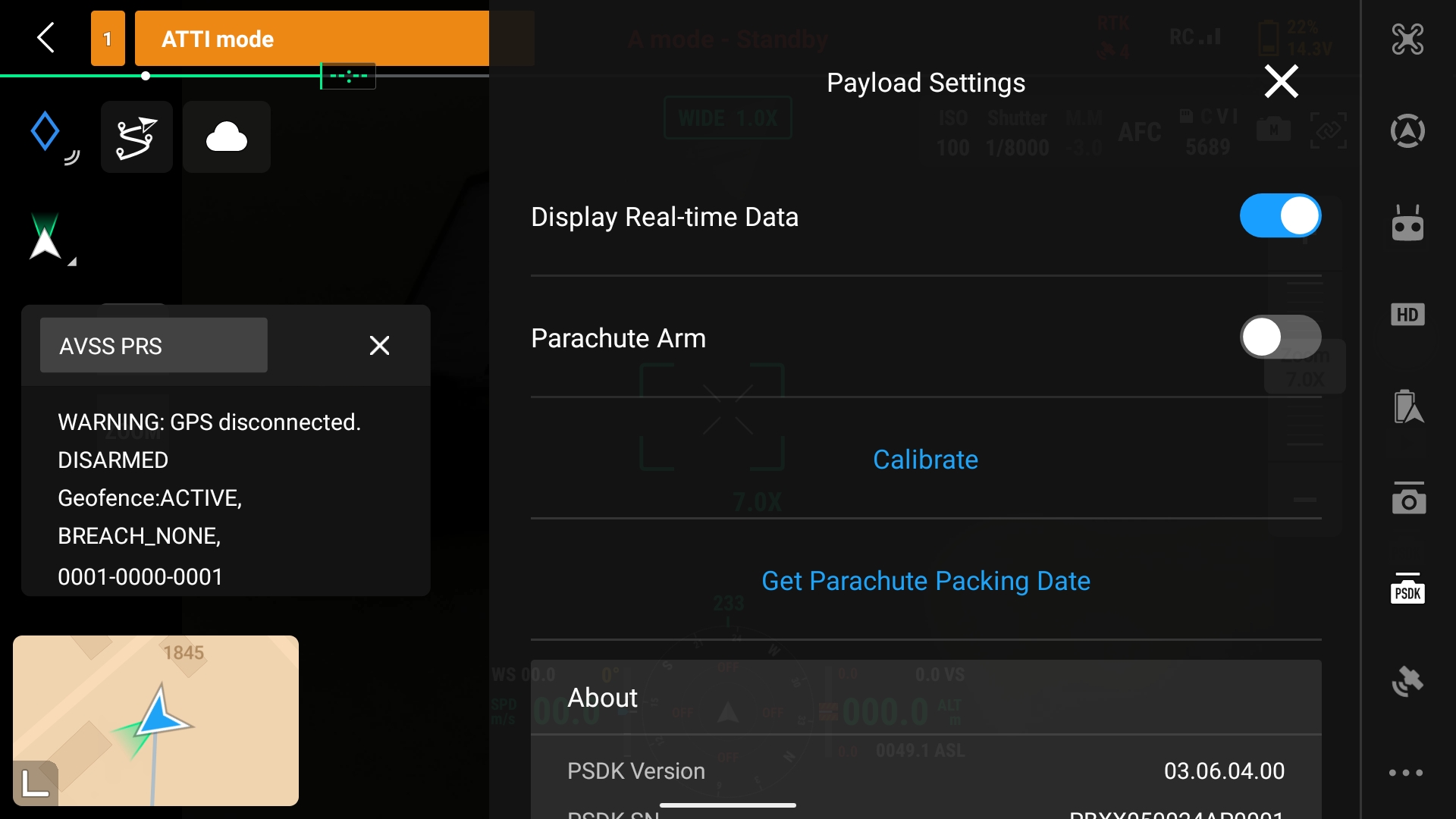
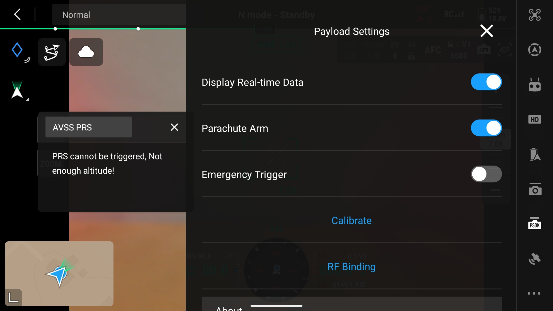
The Manual Triggering Device (MTD) is initiated through the DJI M3D/T transmitter using the PSDK onboard interface. The manual trigger function is provided through the PSDK interface and has a dedicated arm icon/button that must be activated before the parachute can be deployed. To perform a manual trigger of the PRS-M3DTEX, the system will need to be armed (see the "Status Indications" section for instructions), and the deploy button will need to be held down for three (3) seconds. During flight, the PRS-M3DTEX MTD can only be armed once an altitude of 5 metres (16.4 ft) AGL is achieved, as measured by the onboard barometer.
The deploy function can be mapped to buttons on the DJI M3D/T transmitted, which will deploy the parachute immediately if armed (only if using firmware version 3.6.3 or earlier). Any error with the DJI M3D/T will be communicated to the user via the DJI M3D/T transmitter. During the flight, the PRS-M3DTEX ATS will arm itself only once it has reached the minimum deployable barometric altitude above takeoff. Afterwards, if the DJI M3D/T experiences a failure, the ATS detects the failure using a suite of sensors, forces the motors to shut off, and deploys the parachute without the need for pilot input.
The PRS-M3DTEX includes an External FTS (EFTS) module for Enhanced Containment Compliance under MOC2511. The PRS-M3DTEX uses both the PSDK FTS and an additional external FTS module that is installed between the drone and the drone battery. The PRS-M3DTEX EFTS is triggered via a geofence function. This geofence will trigger when armed and when either a user-defined ceiling is breached, or a user-defined boundary is breached. The PRS-M3DTEX has an independent GNSS receiver that measures the position of the drone. The geofence is transferred to the PRS-M3DTEX via a USB-C cable connected to a laptop. See the Geofencingsection for more information on transferring the Geofence.
Maximum number of activations: 266.
The GNSS receiver does not have range limitations; however, the user should define the ceiling based on the maximum Average Mean Sea Level altitude expected over the takeoff altitude
Minimum extent of Ground Risk Buffer: 34 meters (34 meter altitude, wind speed of 1 m/s) 25 + 1.1*W*34/4.34.
The formula below provides a method to calculate the ground risk buffer zone for your operation according to the Specific Operation Risk Assessment. The max altitude (Alt) is based on the operation. The descent rate should be based off the maximum takeoff weight which is 4.34 m/s. There is a 25 meter buffer added to the PRS-M3DTEX geofence, which provides a buffer to avoid unintended triggers of the geofence when flying near the geofence. The wind speed (Wind) is the environmental wind speed for that operation in meters per second (not including gust). The equation is as follows:
The PRS-M3DTEX status, also referenced as “Heartbeat” is indicated using a combination of LED colours. The PRS-M3DTEX status LED is located on the side of the PRS-M3DTEX facing the rear of the DJI M3D/T. The LED colour on the PRS-M3DTEX indicates the stage of the flight.
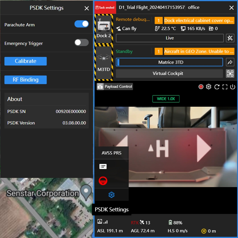
Note that two different user interfaces are presented here. The first, at top, is the interface seen when connecting to the DJI M3D/T through the DJI M3D/T transmitter. The second, at bottom, is the interface seen when connecting to the DJI M3D/T through the DJI FlightHub 2 application.
THE PRS-M3DTEX MANUAL TRIGGER DEVICE CANNOT BE ARMED UNLESS A HEIGHT OF 5 METRES (16.4 FT) AGL IS REACHED.
IF ANY WARNINGS ARE PRESENT, THE PRS WILL NOT ARM. ALWAYS ENSURE THAT ALL WARNINGS DISAPPEAR BEFORE TAKEOFF.
AGL
Above Ground Level.
ATS
Autonomous Triggering System that is independent of any flight critical system of the DJI M3D/T. Used to initiate parachute deployment upon detection of a critical failure of the DJI M3D/T during flight.
Authorized Dealer
An AVSS approved distribution partner who sells the PRS-M3DTEX.
Drone
When referring to a DJI M3D/T, other relevant terms include Aircraft, RPAS, sUAS, UAS, and UAV.
EFTS
External flight termination system, a device that disables power to the drone, and which ensures compliance with EASA MOC 2511.
End-User
The owner of the PRS-M3DTEX who had purchased the system from an AVSS Authorized Dealer.
FTS
Flight Termination System is a device that will disable the propulsion system of the DJI M3D/T.
IP Rating
Ingress Protection Rating.
MTD
The Manual Triggering Device, initiated by arming the PRS through the DJI M3D/T Drone Transmitter. Allows for manual deployment of the PRS-M3DTEX system and is accessed through the Transmitter PSDK Interface.
MDA
The Minimum Deployable Altitude is the lowest altitude at which the PRS-M3DTEX is rated to deploy successfully.
Parachute Pod™
This refers to the non-replaceable Parachute Pod™ that contains the parachute of the AVSS PRS-M3DTEX.
PRS-M3DTEX
The version of the PRS-M3DT parachute recovery system covered in this manual, which contains the external flight termination system (EFTS) for MOC 2511 compliance.
PSDK
Payload Software Development Kit. This is the software application between the drone and the PRS-M3DTEX.
Normal Mode
The PRS-M3DTEX shall be used only in N-mode (Normal): N-mode works best when the GPS signal is strong. The DJI M3D/T utilizes GPS and Forward and Downward Vision Systems to locate itself, automatically stabilize, and navigate between obstacles. Complete details can be found at https://enterprise.dji.com/dock-2/specs.
PRS
As per ASTM F3322, a PRS is a "summation of the components of a parachute recovery system that work to reduce descent velocity."
Shall and Must
“shall” and/or "must" versus “should” versus “may”, v—use of the word “shall” and/or "must" implies that a procedure or statement is mandatory and shall be followed to comply with this specification. “should” implies that this procedure/statement is recommended, and “may” implies that it is optional at the discretion of the supplier, manufacturer, or operator.
Eye Protection
As with any system designed to launch a mass at high velocity, precautions shall be taken to prevent potential injury.
Never point the Parachute Pod™ towards anyone or anything
While the PRS-M3DTEX includes features to prevent unintentional deployments, users shall be aware that the Parachute Pod™ is launched vertically. It is recommended that the operator maintains a clear area of at least five (5) meters (16 feet) after the system has been powered.
Disarming MTD
Always hide the PSDK menu for the MTD before approaching the DJI M3D/T after a landing or in the event of an aborted takeoff.
Ensure PRS-M3DTEX is DISARMED before moving it
Do not pick up the PRS-M3DTEX when it is armed as the sensors may interpret the movements as an in-flight failure. Wait ten (10) seconds for the ATS to disarm.
Error Status
The system should not be used unless it is indicated that no errors are present. The system will not arm itself nor deploy in a failure scenario unless it has initialized successfully.
Parachute Repacking
Only parachutes packed by AVSS are compliant. The Parachute shall be repacked or replaced every twelve (12) months only by AVSS. You will no longer be compliant and will void the warranty if you attempt to repack the Parachute.
Normal Mode and Flight Mode Changes
The ATS is designed to automatically detect abnormal flight behaviors. Flying in a controlled manner and avoiding erratic maneuvers ensures that the PRS-M3DTEX can more accurately distinguish between pilot commands and loss of control. Do not change the flight mode mid-flight as the DJI M3D/T can have a hard/abrupt braking maneuver that can exceed the maximum "25°-degree pitch angle”, as per DJI.
Rules and Regulations
Pilots shall follow the rules and regulations put in place by civil aviation or government bodies in their operating regions.
Energetic Charge Warning
The PRS-M3DTEX utilizes an automotive pyrotechnic as the means of deployment. These charges are similar to that in automobile airbag and seat belt systems. Caution should always be observed around the system. Ensure the System is never pointing towards someone. Note, throughout this document, the pyrotechnic charge is referenced as an "Energetic Charge".
PSDK Interface
The PSDK interface will show the AVSS PRS-M3DTEX user interface. This will allow access to the INFO screen for information on the PRS-M3DTEX, as well as the MTD function of the DJI M3D/T transmitter (or DJI FlightHub 2). The Icon will appear white until the user clicks the icon. This will activate the PSDK window, and turn the icon yellow (blue on DJI FlightHub 2).
Info
The info button will display the status messages window.
Status Messages
The status messages window will allow the user to consult the DJI M3D/T transmitter or DJI FlightHub 2 for information on the PRS-M3DTEX system's health and functionality. This screen will also display the MTD countdown.
Deploy
The deploy function will allow the user to manually trigger the PRS-M3DTEX. This button will need to be held down for three (3) seconds to activate the FTS and the MTD. The status messages screen will also display the MTD countdown. Note that the PRS-M3DTEX must first be armed through the configuration menu (see below) for the MTD to work.
Config.
The configuration function (abbreviated as config.) has two different functions depending on the firmware version.
If using firmware version 3.6.4 or later, it will allow the user to arm the PRS-M3DTEX (see below).
If using firmware version 3.6.3 or earlier, it will allow the user to either arm the PRS-M3DTEX, or to immediately deploy the PRS-M3DTEX using the "Emergency Trigger" function (explained in the "Emergency Trigger Button" section).
In both cases, the configuration function is accessed either through the three dots at the top of the DJI M3D/T transmitter's main screen, or through the gear symbol in the middle of FlightHub 2's main screen.
Onboard Power
The PRS-M3DTEX EM is equipped with an independent capacitor to supply power to the PRS-M3DTEX in the event of a power loss from the DJI M3D/T.
The PRS-M3DTEX EM interfaces and charges directly from the DJI M3D/T on drone startup.
If left in unsuitable environments, the system and/or components may be damaged, the warranty shall be void, and the items may not properly function.
Status
LED Colour Sequence
Required Action
System Error
Consult DJI M3D/T Transmitter for Error Information
Shutting Down the Board
System Reset
Normal Operation and Armed
Normal Operation and Disarmed
PC Mode
SD Mode
Log Dump
Deployment
System Initialization
IMU Calibration
Perform IMU Calibration Steps
FW Update
RF Bind
FTP Mode
Firmware updates must be performed when a new version is released by AVSS. Check the AVSS website regularly for firmware updates, and contact AVSS customer support if you have any questions.
If a new firmware update is required, an email will be sent from the AVSS support team informing all users that an update is needed. Users can then visit the AVSS website (URL https://www.avss.co/), navigate to "Products" - "Drone Parachute Recovery Systems" and click on the relevant product page to see the updated firmware file. The file will be in a ZIP format with the version indicated in the title, as shown below:
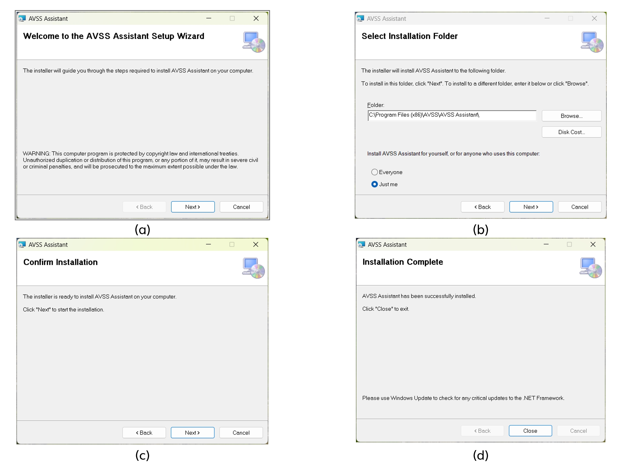
Upon accessing and downloading the latest firmware file, users can then import the firmware update onto their PRS using the AVSS Assistant. The AVSS Assistant can be downloaded from the AVSS website (usually in a ZIP format file). The current version number of the software will be included in the file name, as shown below.
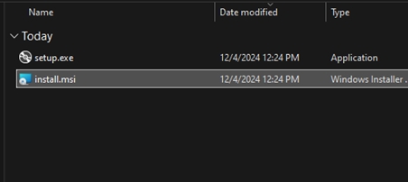
The AVSS Assistant can then be installed on a local computer by extracting the "setup.exe" file (as indicated below) and following the installation instructions (also indicated below).
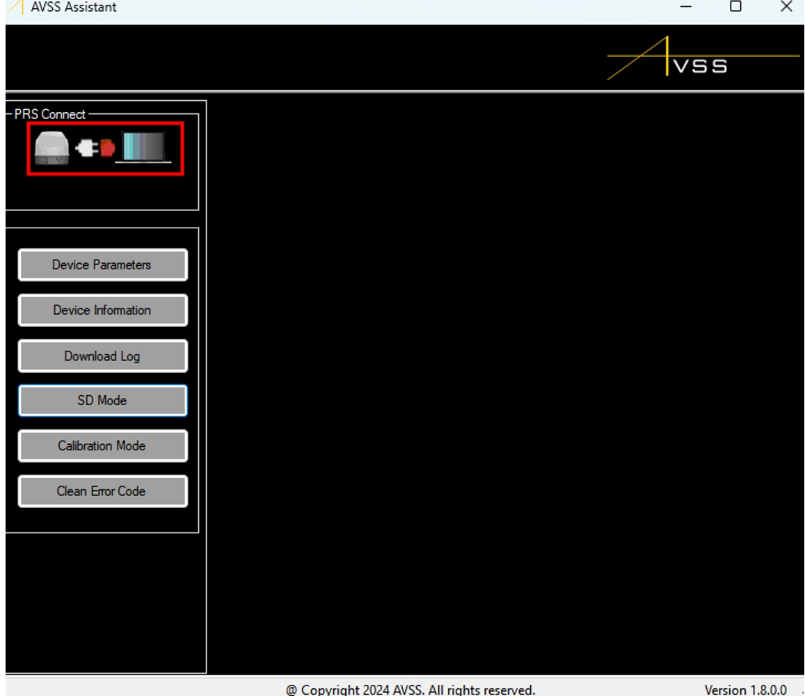
Upon completing the installation, users should see the following screen when they open the AVSS Assistant. The red coloring of the charging cord in the "PRS Connect" box (at top left of screen) indicates that there is presently no PRS-M3DTEX attached to the computer. If the PRS-M3DTEX is connected via USB cord to the computer (see second image below), this icon will turn green to indicate a successful connection.
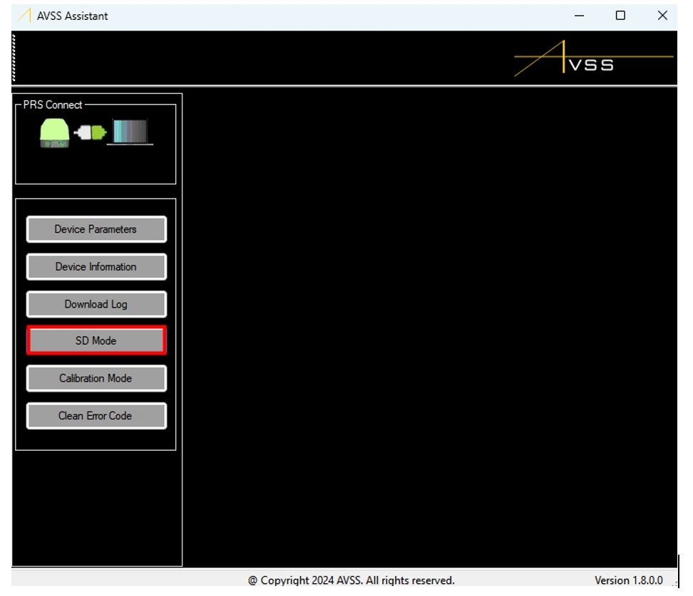
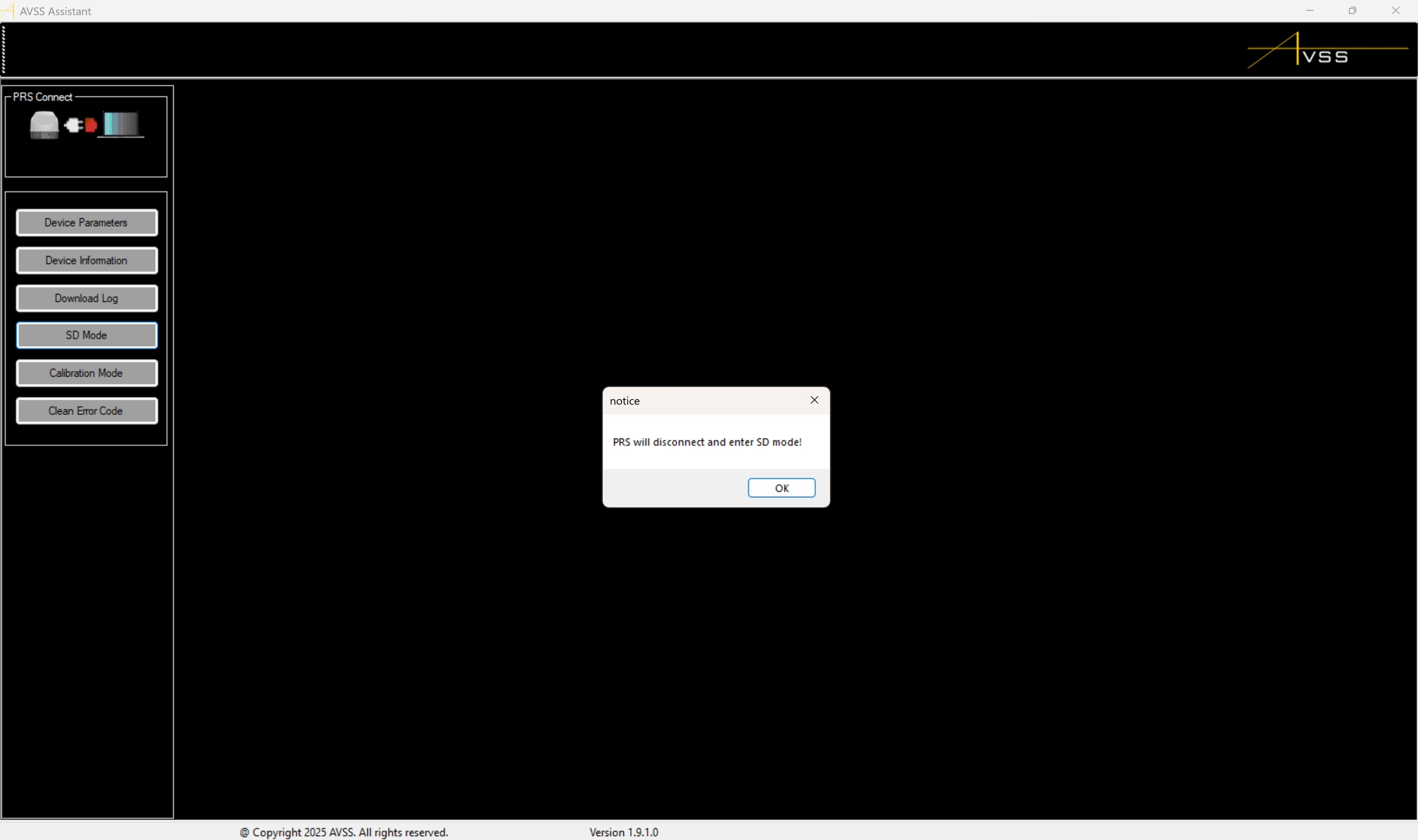
Upon a successful connection between the PRS-M3DTEX and the AVSS Assistant program, the updated firmware file can be imported into the PRS-M3DTEX by first placing the PRS-M3DTEX into "SD Mode".
Once the PRS-M3DTEX is placed into "SD Mode", the PRS-M3DTEX should automatically disconnect from the local computer, which is indicated to the user with a dialog box.
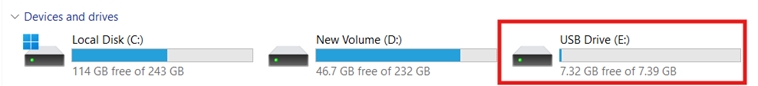
When in "SD Mode", the PRS-M3DTEX acts as a standard USB device, where its file directory is visible as an external connection to the local computer.
To apply the firmware update, simply navigate to the .sfb files (located within the updated firmware's ZIP file) and copy/paste these files into the PRS-M3DTEX's main directory.
Upon pasting the firmware update into the PRS-M3DTEX's main directory, the user should close the SD card directory window and then cycle the PRS-M3DTEX's power by unplugging the PRS-M3DTEX from the computer and then re-plugging it in.
ENSURE THAT THE PRS-M3DTEX'S SD CARD DIRECTORY WINDOW IS CLOSED PRIOR TO DISCONNECTING THE PRS-M3DTEX FROM THE COMPUTER TO AVOID CORRUPTING THE PRS-M3DTEX SD CARD.
The PRS-M3DTEX will then update the firmware accordingly, which is indicated to the user by the PRS-M3DTEX's status LED displaying as white.
DO NOT DISCONNECT THE PRS-M3DTEX FROM THE LAPTOP WHILE THE STATUS LIGHT IS WHITE, AS THIS WILL PREVENT THE UPDATE FROM COMPLETING SUCCESSFULLY.
Upon successful completion of the firmware update, the PRS-M3DTEX status light will change from white to green. Leave the PRS-M3DTEX connected to the computer and navigate to the "Device Information" tab in AVSS Assistant to verify the current firmware version.
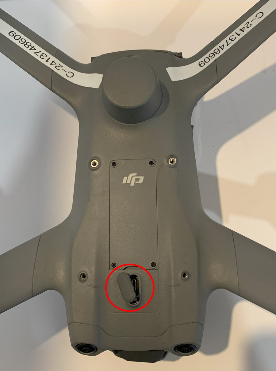
Ensure that the PRS-M3DTEX is off before attaching and/or disconnecting the PRS-M3DTEX from the DJI M3D/T
A set of gloves and a packet of grease like those displayed below should be provided along with the PRS-M3DTEX. Contact AVSS if these items are not present.
NOTE: STEP 1 OF THE BELOW INSTRUCTIONS MUST BE REPEATED FOR ALL SUBSEQUENT INSTALLATIONS OR AFTER A RE-PACK IS CONDUCTED.
DO NOT ATTACH THE PRS-M3DTEX SLEEVE AND DJI M3D/T BATTERY TOGETHER PRIOR TO INSERTING THE PRS-M3DTEX SLEEVE INTO THE DJI M3D/T BATTERY COMPARTMENT.
Step 1
Grease the Gasket on the PRS-M3DTEX Sleeve
Open the clips on the PRS-M3DTEX sleeve to access the gasket track. Generously apply a layer of grease on the surface of the gasket while ensuring that the gloves provided are covering your hands.
Step 2
Position the PRS-M3DTEX Sleeve in the Battery Compartment
Slide the newly greased PRS-M3DTEX sleeve into the battery compartment using light and even pressure until the PRS-M3DTEX sleeve clips can be locked into place.
Step 3
Seal the Clips on the PRS-M3DTEX Sleeve
Gently push the black clips on each side of the PRS-M3DTEX sleeve inward (toward the DJI M3D/T) to secure the PRS-M3DTEX sleeve within the battery compartment. A successful connection will be signaled by a light click.
Step 4
Insert the DJI M3D/T Battery Into Its Compartment
Gently push the DJI M3D/T battery backward into its compartment as shown. Exercise caution to avoid damaging the gasket track on the PRS-M3DTEX sleeve. The battery is fully secured in place when a light click is heard.
Step 5
Position the PRS-M3DTEX Sleeve Cable
Prior to installing the PRS-M3DTEX enclosure itself on top of the DJI M3D/T, ensure that the PRS-M3DTEX sleeve cable is positioned over top of the front left arm of the DJI M3D/T (bottom right in the image at right). Do not pull or tug the cable.
Step 6
Locate the Forward Gasket Door on the Drone
In order for the PRS-M3DTEX enclosure to be properly installed on the DJI M3D/T the forward gasket door needs to be opened and properly positioned.
Step 7
Open the Forward Gasket Door
Open the forward gasket door, and align the stem of the door with the notch in the base of the PRS-M3DTEX as shown.
Step 8
Insert PRS Into PSDK Port
Install the PRS-M3DTEX onto the DJI M3D/T. Ensure the orientation is correct, and that the PSDK USB-C connection is lined up.
*The arrow at right indicates the nose of the drone. **The gasket on the PSDK connection will not allow the PRS-M3DTEX to be properly seated until the mounting screws, which hold the unit down, are installed in Step 13.
Step 9
Hardware Check
Verify that all of the included hardware is present. This includes two shorter M3x8mm (QTY2) screws for the back of the PRS-M3DTEX. and an additional strap for securing the front of the PRS-M3DTEX. The strap contains pre-installed inserts (QTY 2) and pre-installed M3x16mm (QTY 2) screws (shown at right).
Step 10
Install Rear Screws Into PRS
Install the M3 x 8 mm screws (QTY 2) through the back holes of the PRS-M3DTEX into the drone as illustrated to secure the back of the PRS-M3DTEX to the top of the drone. Ensure the screws are tightly secured.
Step 11
Double Check That Mounting Insert Is Pre-Installed Into Strap
Double-check that both the included inserts (QTY 2) and longer M3x16 screws (QTY 2) are pre-installed into the ends of the PRS-M3DTEX straps as illustrated.
Step 12
Position Straps Around Forward Arms
Loop the PRS-M3DTEX straps underneath the forward arms of the DJI M3D/T and insert the ends of the straps into the mounting holes as shown at right.
Step 13
Install Mounting Screws
Finish installing the PRS-M3DTEX using the M3x16mm (QTY2) screws to secure the front of the PRS-M3DTEX to the top of the drone. The installation holes used are located at the front/closest to the drone's camera, as shown at right. Ensure the screws are tightly secured.
Step 14
Power On Drone/PRS
To turn on the PRS-M3DTEX, you will need to turn on the DJI M3D/T drone.
Step 15
Check Continuity
Check for system continuity and errors on the DJI M3D/T transmitter. This will be indicated by the PSDK symbol on the right-hand side of the transmitter's screen when in the camera view.
Step 16
Power Off Drone/PRS
Power off the DJI M3D/T. The PRS-M3DTEX will take up to ten (10) seconds for the LED to turn off. Once the LED is off the PRS is safe to approach. Do not unplug or move the DJI M3D/T or PRS-M3DTEX until the PRS-M3DTEX is turned off.
DURING REMOVAL, IT IS POSSIBLE THAT THE STRAP AND ASSOCIATED HARDWARE (QTY 2 PRE-INSTALLED INSERTS AND QTY 2 PRE-INSTALLED M3x16MM SCREWS) WILL BECOME STUCK IN THE MOUNTING HOLES. IF THIS OCCURS, EITHER CAREFULLY LOOSEN THE SCREWS FURTHER OR GENTLY MOVE THE STRAP FROM SIDE TO SIDE TO RELIEVE PRESSURE ON THE ENDS. DO NOT PULL EXCESSIVELY ON THE STRAP TO TRY AND FORCE IT OUT.
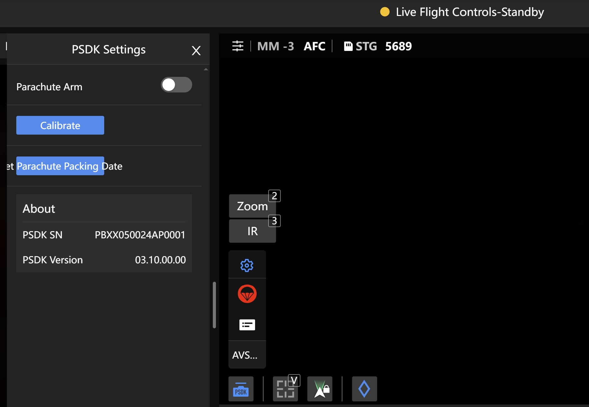
As discussed previously in the "" section, an additional "Emergency Trigger" function exists for the user in the configuration menu if using firmware version 3.6.3 or earlier. If activated, this function will deploy the PRS-M3DTEX immediately if the system is armed and the button is pressed. This differs from the "deploy" button on the main status screen, which must be held down for 3 seconds prior to the PRS-M3DTEX deploying.
Examples of the original configuration menu interface with the "Emergency Trigger" option included are attached below:
Extreme caution must be exercised if operating the PRS-M3DTEX with version 3.6.3 or earlier, as the parachute will deploy if the "parachute arm" and "emergency trigger" functions are both toggled on. As such, users shall ensure that the "Emergency Trigger" option is toggled off at all times before and during flight.
All customers must perform a firmware update to version 3.6.4, which no longer includes the Emergency Trigger interface.
As well, if using version 3.6.3 or earlier, the "RF binding" function displayed in the above images is an obsolete function and shall be ignored.
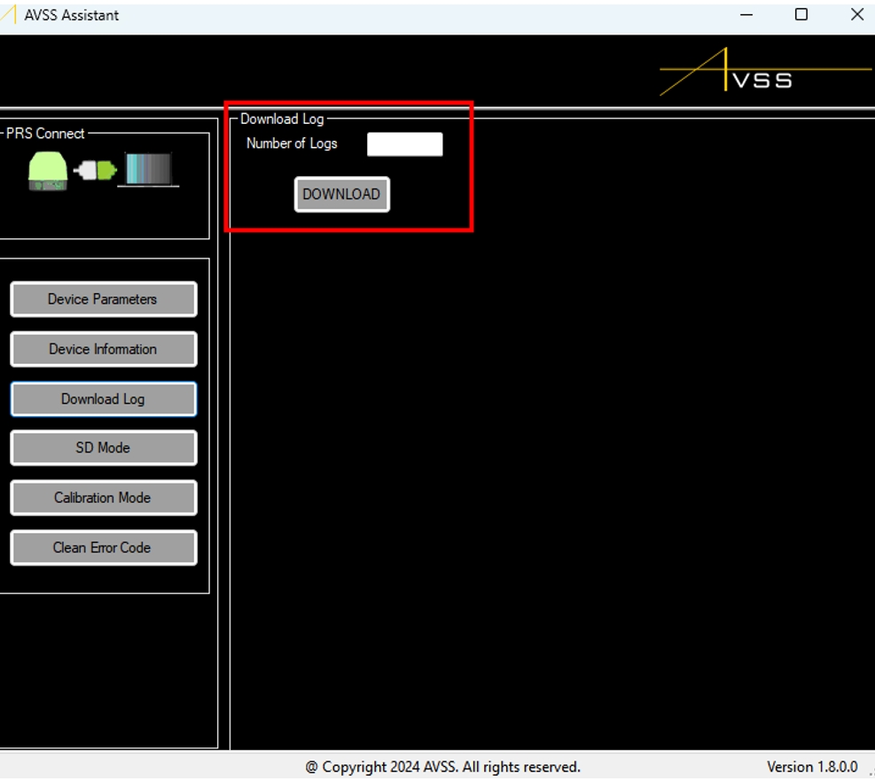
The AVSS Assistant also contains a function to download flight logs to a local computer. To initiate this process, click on the “Download Log” button. A new box “Download Log” will appear. In the “Number of Logs” box type the number of the most recent logs that are to be downloaded and click on the “DOWNLOAD” button. The download will always start from the most recent log and work backward.
At this time, the PRS-M3DTEX will disconnect from the AVSS Assistant application and initiate the log recovery and transfer indicated by the blinking blue colour of the PRS LED. This process might take several minutes.
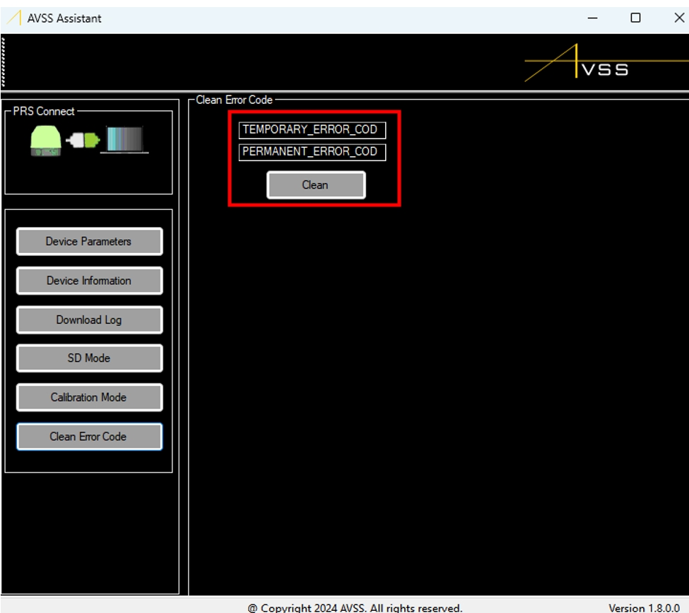
Error codes will appear on the PRS-M3DTEX whenever a critical error occurs in flight. These error codes will appear in the PSDK display window until they have been cleared. When a critical error shows up, contact AVSS first. After AVSS analyzes the error, if it is safe to do so, you will be advised to manually clear the error.
To clear the error, click on the “Clean Error Code” and click on the “Clean” button.
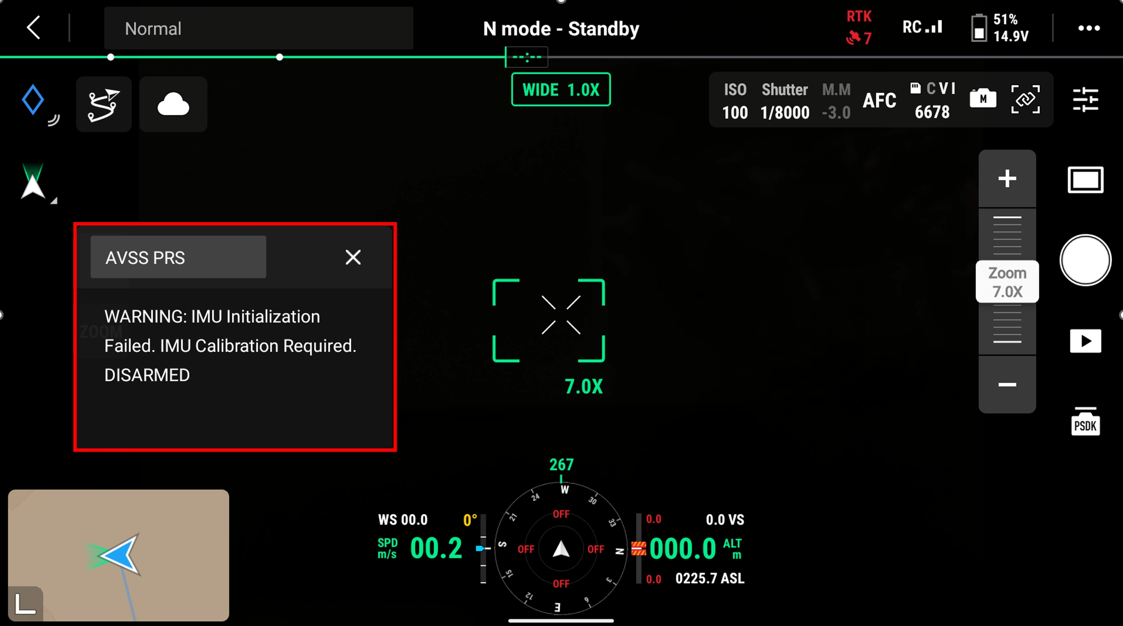
Regardless of whether the DJI M3D/T flight transmitter or DJI FlightHub 2 is used as the control method, the configuration menu contains two additional options not described above - calibration and parachute packing date. The parachute packing date option (only available for firmware version 3.6.4 or later) allows the user to see when their parachute is due to be re-packed (see the "" section for further information on re-packing timelines). The calibration option (available for all firmware versions) is used to re-calibrate the inertial measurement unit (IMU) of the PRS-M3DTEX.
In the event an IMU calibration is required, the following message will become visible on the main screen of the DJI M3D/T flight transmitter or of DJI FlightHub 2. This is also indicated on the PRS-M3DTEX itself by the status LED, which will flash yellow (see chart at top of "" section).
To properly calibrate the IMU, the PRS-M3DTEX must be rotated through the six physical orientations, with a minimum of five (5) seconds spent in each orientation. Note that this actually results in seven (7) changes in orientation. The easiest way to accomplish this is simply to rotate the DJI M3D/T through each orientation with the PRS-M3DTEX attached, as shown below.
PRIOR TO ROTATING THE DJI M3D/T, CHECK THAT THE PRS-M3DTEX IS DISARMED BY ENSURING THAT THE PRS STATUS MESSAGE OUTLINED ABOVE READS "DISARMED".
After an additional thirty (30) seconds, a successful calibration will be signaled by the disappearance of the calibration warning from the main screen of either the DJI M3D/T transmitter or DJI FlightHub 2. The LED status light will also change to green to indicate normal operations. If a successful calibration is not indicated, restart the DJI M3D/T to re-pair the PRS-M3DTEX with the DJI-M3D/T.
Independently, the DJI M3D/T may prompt a user that the on-board compass needs to be calibrated. In this case, a user shall simply follow the instructions displayed either on the DJI M3D/T transmitter screen or in FlightHub 2. It is recommended that while calibrating the compass, the PRS-M3DTEX be attached to the DJI M3D/T to avoid changes to the DJI M3D/T's magnetic field readings.
IF CALIBRATING THE DJI M3D/T COMPASS WITH THE PRS-M3DTEX ATTACHED, CHECK THAT THE PRS-M3DTEX IS DISARMED BY ENSURING THAT THE PRS STATUS MESSAGE OUTLINED ABOVE READS "DISARMED".
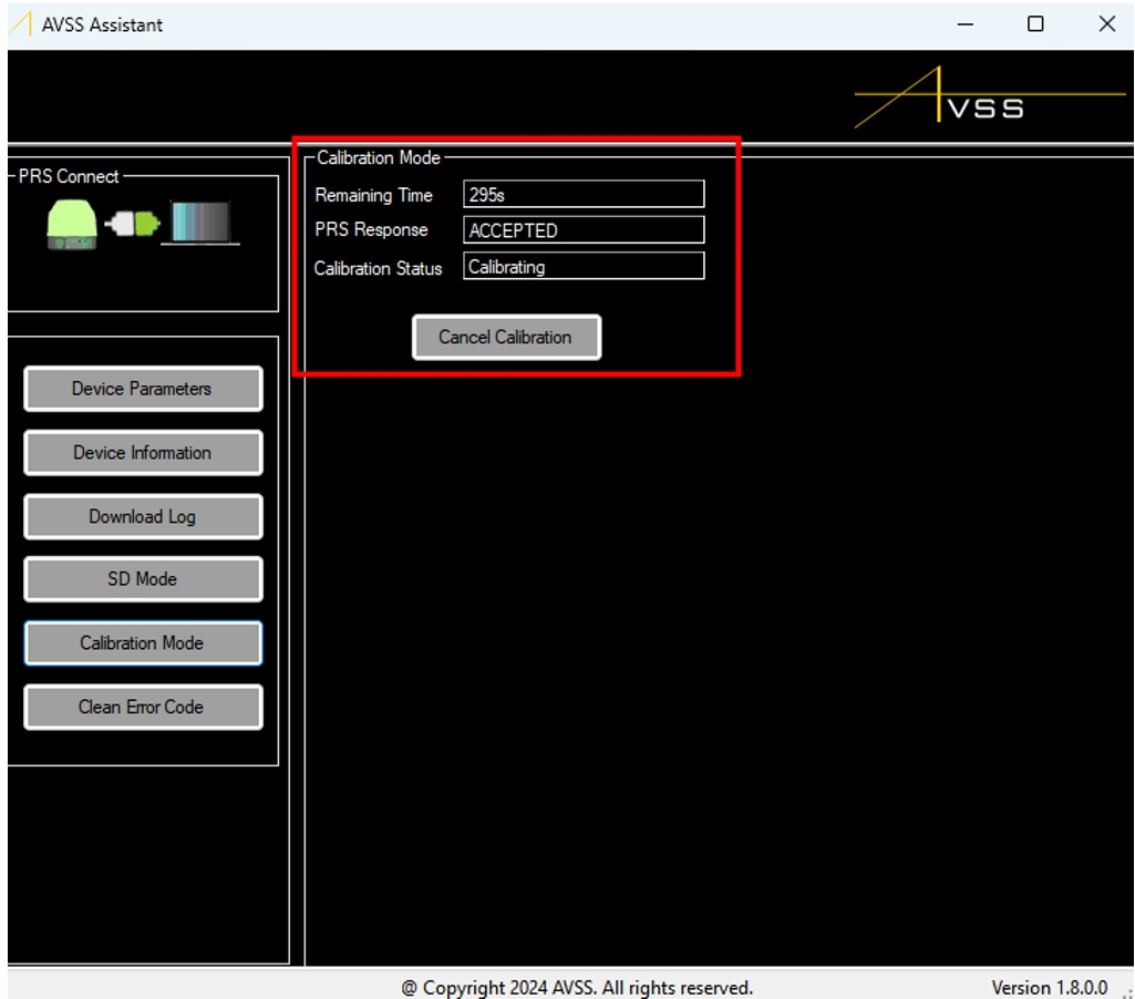
It is also possible to calibrate the PRS-M3DTEX's IMU by using the "Calibrate Mode" function in AVSS Assistant. To access this feature, click on the “Calibration Mode” button to calibrate the PRS’s sensors. Note that if using this option, there is a 300-second time window to complete the calibration maneuver; otherwise, the calibration is automatically cancelled.
As with conducting a calibration from the DJI M3D/T transmitter, imagine the PRS-M3DTEX as being inside of a 3D cube and place the PRS-M3DTEX on every 6 faces of this cube. Keep the PRS-M3DTEX stationary for 10 seconds on every face. In the end, return the PRS to its initial orientation and wait 10 seconds. If the calibration is successful, the PRS-M3DTEX will restart. If a successful calibration is not indicated, restart the DJI M3D/T to re-pair the PRS-M3DTEX with the DJI-M3D/T.
When the logs have been downloaded, the PRS-M3DTEX will enter "SD mode" as indicated by a solid blue LED color. As outlined previously in the section, once placed in "SD mode", the contents of the PRS-M3DTEX's SD card will be accessible as a USB drive on your local computer. This drive contains the flight logs in the “event_log” and “onboard_flash” folders.
The PRS-M3DTEX performs an automatic pre-flight FTS diagnostic check on each startup of the system
The diagnostic verifies that the FTS functionality is operational without shutting down the drone.
If the diagnostic fails, the PRS will send a "WARNING: EFTS Diagnose Failed" message to the DJI transmitter and/or Flight Hub 2 PSDK Window.
If the diagnostic passes, there will no messages about the Diagnostic.
DO NOT HANDLE OR MOVE THE DJI M3D/T ONCE THE PRS-M3DTEX IS TURNED ON UNLESS CALIBRATING EITHER THE PRS-M3DTEX IMU OR THE DJI M3D/T COMPASS. REFER TO THE "CALIBRATION PROCESSES" SECTION FOR INSTRUCTIONS ON HOW TO CALIBRATE EACH OF THESE COMPONENTS.
AUTO-TRIGGER WILL ONLY ARM ONCE AN ALTITUDE OF 34 METERS (111.15 FT) IS REACHED.
MANUAL TRIGGER DEVICE CAN ONLY BE ARMED ONCE AN ALTITUDE OF 5 METRES (16.4 FT) IS REACHED
THE MINIMUM DEPLOYABLE ALTITUDE FOR THE PRS-M3DTEX IS 34.8 METERS. WHEN OPERATING OVER PEOPLE, DO NOT FLY BELOW THE 34.8 METERS (114.17 FEET).
ENSURE THE PRS-M3DTEX LED IS OFF BEFORE HANDLING THE DJI M3D/T.
The Parachute Pod™ must be repacked every twelve (12) months. To return a used and/or unused PRS-M3DTEX, an end-user may do so by sending the PRS-M3DTEX directly to AVSS or by returning the PRS-M3DTEX to their Authorized Dealer.
Sending to AVSS:
Before sending the PRS-M3DTEX to AVSS, contact customersupport@avss.co to request a shipping label and to order a replacement unit.
To return your PRS-M3DTEX, utilize the same box the replacement unit arrives in, with the provided shipping label to send the PRS-M3DTEX to AVSS.
Once AVSS receives the PRS-M3DTEX and completes the visual inspection, you will be notified and will receive your deposit within fourteen (14) business days.
Sending to an Authorized Dealer:
Contact your Authorized Dealer to notify them that you will be returning and/or requesting a new PRS-M3DTEX.
Maintenance and inspection intervals of the AVSS PRS-M3DTEX are required to maximize the safety of each flight and ensure proper functionality for parachute deployment whenever it may be required. The PRS-M3DTEX’s Parachute Pod™ is intended as a single-use item that must be repacked in either twelve (12) month intervals, or after a deployment.
Visually inspect the PRS-M3DTEX to ensure there is no damage.
Always ensure the power is off.
Make sure the unit is clean and dry before putting in the case.
Store in a dry room that is at room temperature.
Uninstall the AVSS PRS-M3DTEX assembly from the DJI M3D/T drone.
Visually inspect the USB-C located on the underside of the PRS-M3DTEX. Check against signs of corrosion, dust/dirt buildup, wear, or any other types of abnormalities.
Inspect the strap attachment and verify the mounting screw remains secured, and that the strap is free of damage.
If any of the above defects are present during the 18 month inspection period, contact AVSS for further information.
MAKE SURE ALL CONNECTORS ARE PROPERLY ATTACHED THE EFTS Module, AND PRS-M3DTEX
TO DETACH FLIGHT TERMINATION SYSTEM, REMOVE THE PRS FROM THE TOP OF THE DRONE, THEN UNCLIP THE BATTERY CLIPS ON THE BATTERY. GENTLY SLIDE THE BATTERY FROM THE DJI M3D/T COMPARTMENT.
Do not leave metal terminals exposed to open air when not in use .
After exceeding the maximum number of FTS activations contact AVSS to determine if a servicing of the FTS is required.
Always update the PRS-M3DTEX to the latest firmware version
AVSS warrants that the PRS-M3DTEX and its accessories are free from defects and fit for the operational purpose intended.
The warranty period for the PRS-M3DTEX is, the earliest of, twelve (12) months after purchase, or after three Parachute Pod™ deployments, which starts on the date listed as per the user’s invoice from an Authorized Dealer.
The PRS-M3DTEX is limited to a maximum of 3 deployments and may be retired after fewer deployments at the sole discretion of AVSS. In the case of a deployment, the PRS must be shipped to AVSS's location for analysis. Any costs for non-reusable parts that must be replaced may be incurred by the end-user at the sole discretion of AVSS.
This warranty requires the PRS-M3DTEX to be shipped to AVSS’s location for analysis and may either be fixed, replaced and/or deemed voided of warranty at the sole discretion of AVSS.
After a deployment, the customer must send AVSS the following files:
PRS-M3DTEX data
DJI M3D/T DAT data
DJI M3D/T text file
If the PRS-M3DTEX is deemed void, the cost of analysis and shipping shall be the responsibility of the end-user. Nothing herein contained shall be construed to exclude or limit any warranty, express or implied by law.
AVSS hereby declares that the warranty shall be deemed void if the PRS-M3DTEX is not used for the intended operational uses and/or if alterations, tampering, or any actions deemed comprising by AVSS, directly or indirectly, are performed to the PRS-M3DTEX. This includes, but is not limited to, non-standard use, the use of potentially disabling anti-operations technology, and/or unintended damage by the end-user.
The product warranty does not cover water damage.
If the product is used or handled in any way otherwise described within this user manual, the warranty shall be void.
The PRS-M3DTEX purpose is to assist in decreasing the ground impact energy caused by a mid-flight failure of the DJI M3D/T. Under no circumstances can the end-user pursue any compensation or allowance from AVSS if their DJI M3D/T is damaged.
It is the responsibility of the purchaser to keep up to date using the AVSS wiki to ensure the most recent user manual is being referenced. AVSS is not responsible if PDF copies of the user manual are being referenced that contain outdated information.
1
How do I register my PRS-M3DTEX?
Go to .
2
When does the ATS Arm?
34 meters (111.5 ft).
3
When does the PRS-M3DTEX return to a standby state?
The ATS disarms when the DJI-M3TD is within five (5) meters (16 feet) of the ground. If this sensor is not available then the ATS will disarm after landing for five (5) seconds.
4
Is the PRS-M3DTEX compatible with Flight Hub 2?
Yes, the PRS-M3DTEX is compatible with any cloud API that has integrated the PSDK, including Flight Hub 2.
This feature is only applicable for PRS-M3DTEX users who are running firmware version 3.6.4 or later.
DJI has not yet released the functionality in the FlightHub 2 platform to export Custom Task Areas (i.e., geofences). This document will be updated when this feature is released. Meanwhile, AVSS PRS-M3DTEX users can use the QGroundControl platform to design their desired geofence and import it to the AVSS PRS-M3DTEX.
This instruction set assumes that the user has already designed a geofence in FlightHub 2. For instructions on how to design a geofence in FlightHub 2, refer to the DJI FlightHub 2 user manual at the following link: https://fh.dji.com/user-manual/en/overview.html
Follow the instructions at the link below to install the QGroundControl platform onto a local computer: https://docs.qgroundcontrol.com/master/en/qgc-user-guide/getting_started/download_and_install.html
If prompted to select a firmware and vehicle type during the process, ensure that "PX4 Pro" and "Multi-Rotor" are both selected.
Open QGroundControl and then click the “Fly Plan” icon to create the Geofence.
Refer to the instructions at the link below to design the desired geofence:
https://docs.qgroundcontrol.com/master/en/qgc-user-guide/plan_view/plan_geofence.html
Ensure that "inclusion" is selected as the Fence type, as this will match the green “Custom Task Area” in DJI Flight Hub 2. Ensure that your fence matches the fence created in DJI Flight Hub 2 as closely as possible.
The following link shows how to export the designed geofence. Please save the geofence file as “PX4_mission.plan” as this is the name that the AVSS PRS recognizes as its current geofence mission.
https://docs.qgroundcontrol.com/master/en/qgc-user-guide/plan_view/plan_view.html
As outlined previously in the "Firmware Updates" section of this manual, firmware updates are conducted by connecting the PRS to a local computer, accessing AVSS Assistant and placing the PRS into "SD mode". These steps are repeated here.
Similar to a firmware update, the user will then copy-pase the geofence file exported in the previous step (labeled as "PX4_mission.plan") into the main directory of the PRS's SD card.
After successfully transferring the geofence file to the PRS SD Card storage, cycle the power of the PRS by unplugging the PRS fron the computer and then re-plugging it in.
ENSURE THAT THE PRS'S SD CARD DIRECTORY WINDOW IS CLOSED PRIOR TO DISCONNECTING THE PRS FROM THE COMPUTER TO AVOID CORRUPTING THE PRS SD CARD.
Upon re-connecting the PRS to the computer, follow the process detailed in the "Firmware Updates" section of this manual to put the PRS into "SD mode".
Once in "SD mode", navigate to the latest event log"
When checking the event log, use the actual log number (e.g. 000008) as a guide to the most recent event log instead of the calendar date on the log file. A higher number indicates a more recent log.
Ensure that the geofence information in the event log (i.e. shape, coordinates) is consistent with the key information in the "PX4_mission.plan" file. Note that the first two images shown below correspond to a circular geofence and the next two images correspond to a polygon geofence.
Once the geofence information on the PRS is confirmed, the user can install the PRS-M3DTEX on the DJI drone and check the status of the Geofence triggering function on the remote using the DJI Pilot float window. The following status indications will be shown in the window.
Status
Possible Values
geofence_mission_status
GEOFENCE_IDLE: When no geofence mission is set
GEOFENCE_SYNCING: When PRS synchronizes the geofence information with the drone
GEOFENCE_RUNNING: When the geofence triggering function is active and running
GEOFENCE_ERROR: When geofence information has an error
geofence_breach_status
BREACH_NONE: When no geofence breach has happened
BREACH_MINALT: When a geofence breach happened due to violating minimum altitude
BREACH_MAXALT: When a geofence breach happened due to violating maximum altitude
BREACH_BOUNDARY: When a geofence breach happened due to crossing a boundary
geofence_id
mission_opaque_id,
geofence_circle_count,
geofence_polygon_count
in the following format: “%04d-%04d-%04d”
Polygon geofences must have fewer than 50 vertices in total. Circle geofences must have fewer than 15. If these limits are exceeded, the PRS-M3DTEX will fail to fully import the geofence information and record one of the following messages in the event log: "The geofence file is too large to import", or "Out of memory. DISARMED".
Arming and Disarming: Auto arming/disarming conditions of the Geofence triggering function are the same as ATS’s. Please also note that when the geofence triggering function is armed, the drone must have already been in an inclusive geofence and outside of exclusive geofences. Therefore, make sure the whole flight from takeoff to land stays in an inclusive geofence zone and outside of any exclusive geofence zone.
VERTICAL_BUFFER_BASELINE and HORIZONTAL_BUFFER_BASELINE: The geofence triggering function in PRS considers a vertical and horizontal buffer at the boundaries of the geofences where the parachute deployment command is masked. The baseline values for vertical and horizontal buffers are 30m and 20m, respectively. However, note that if the onboard GNSS module of the PRS estimates that vertical or horizontal accuracies are better, those values DO NOT overwrite the baseline values. For instance, if the GNSS module estimates that the vertical positioning accuracy is 25m, the vertical buffer is still the baseline value of 30m; however, if the GNSS module estimates that the horizontal positioning accuracy is 25m, the horizontal buffer will be set to 25s instead of the baseline value of 20m.
GEOFENCE_TRIGER_DELAY: If the drone crosses the geofence boundary and also passes the buffer distance discussed before, the pilot has 5 seconds to react and bring the drone back to a safe zone before the parachute is deployed.
VERTICAL_BUFFER_MAXIMUM and HORIZONTAL_BUFFER_MAXIMUM: If the onboard GNSS positioning error grows above a certain threshold, the PRS will disable the Geofence trigger function. The vertical and horizontal thresholds are 50m and 30m, respectively.
The maximum altitude is based off of the Barometric Altitude Above Takeoff provided by the onboard barometer. To set the ceiling of the PRS open the AVSS Assistant software and connect the PRS to the computer via the provided USB-C cable.
After connecting to the PRS, click “Device Parameters”
Then set the ceiling by adding a value in meters Above Takeoff Level in the “Set Maximum Safety Height” text box, then click “SET”. You should see the “Maximum Safety Height” change in the list of parameters above.
When planning a mission, provide a sufficient buffer in the altitude so that you clear any elevations in the terrain in your flight area.
When setting the Maximum Safety Height, consider the highest building/elevation point within the flight plan so that the Altitude Above Takeoff is never greater than the Maximum Safety Height.
Email:
Days of Operation:
Monday to Friday, excluding holidays
Hours of Operation:
10:00 am Est to 4:00 pm Est
Telephone:
+1-844-852-0665